Case in short
Question
A sailmaker wanted to save drawing time: cutting shapes for boat covers, such as overlaps, zip flaps and hems, were drawn by hand from panels coming out of a 3D scan.
Approach
StudioFG wrote scripts that read the designer's lines per layer and turn them automatically into hems and other cutting shapes, and that make the orientation of all scanned panels consistent.
Result
Years later the scripts are still in use and work on every drawing, whether polylines or NURBS curves.
A sail maker approached StudioFG with the question whether certain cutting shapes could be generated automatically from his drawing in order to save time.
Among other things, the client makes boat covers, which are measured using a 3D scanner. Drawings are made on the basis of a few points from the 3D scan, which are then cut out by a CNC cutting machine. For overlapping parts, flaps for zippers and other shapes, certain cutting lines have to be generated from these panels.
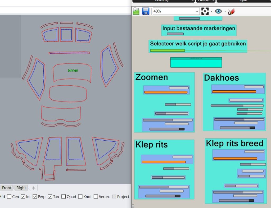
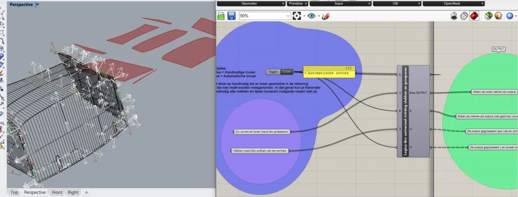
The designer of the boat cover can divide certain lines into layers. These are automatically loaded and converted to hems for example. 4 layers can divine 4 different types of parts.
A second challange was solving the orientation of all panels that came out of the 3D scan. Some panels had a main orientation inwards, while others had a ‘normal’ orientation outwards. For this purpose, a script was developed that analysed all surfaces and makes them universal in direction.
The project was completed in about 2 weeks. More than a year later, the scripts are still in use and work successfully on all the drawings to which it has been applied. Regardless of the geometry.
Automate repetitive drawing work?
StudioFG builds scripts and integrations that generate drawings and production data automatically.